Now let’s use real microprocessor.
For this project we will need microprocessor, programmer and scheme with LED which we used in Arduino and Raspberry Pi projects.
Also prerequisite is that you completed project in part I.
We can split microprocessor development into several steps:
1 – write and compile a program
2 – verify it on simulation software (optional)
3 – write compiled program on microprocessor
4 – test it
In the part I we completed steps 1 and 2. Now we are going to do 3 and 4.
Let’s proceed.
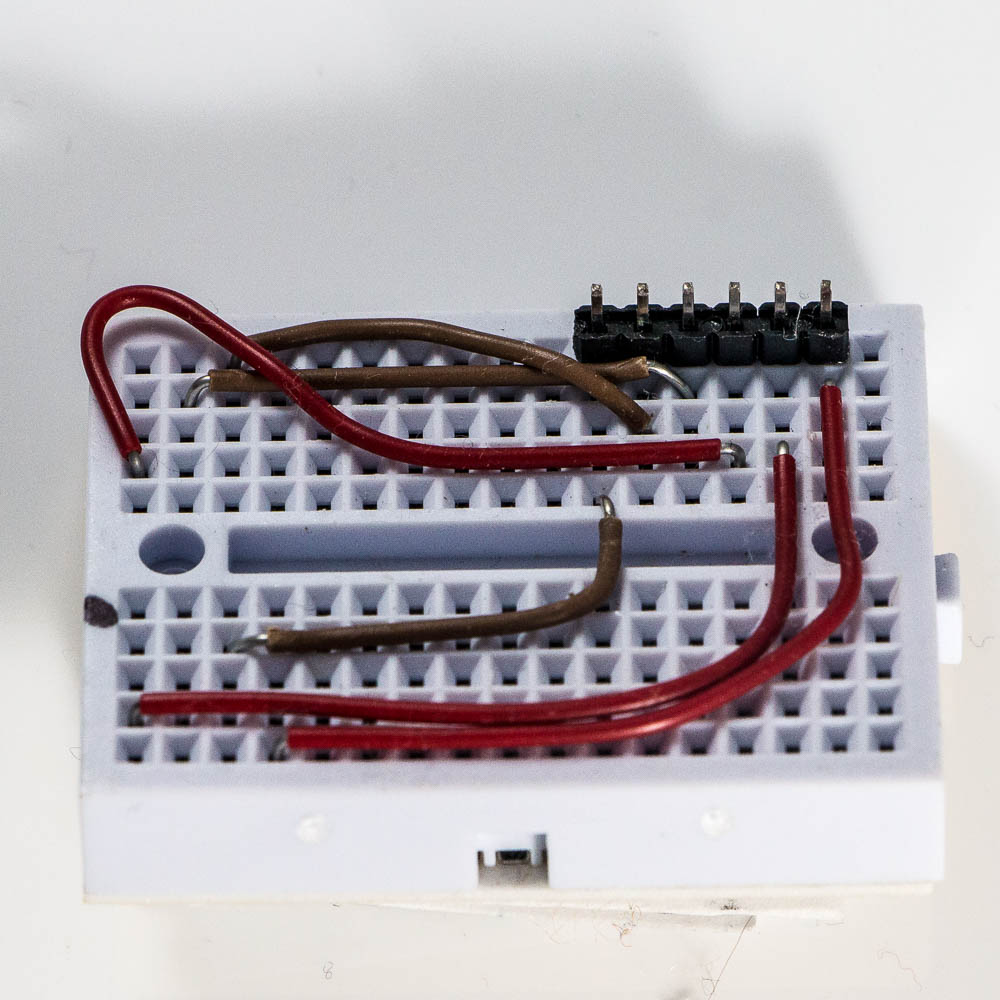
For step 3 you will need a programmer and a breadboard to connect programmer to microprocessor:
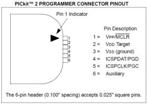
Please note that programmer I am using is an older version than link I provided – version 2.
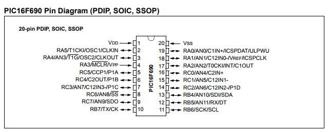
And what have I done here? Basically you need connect PICKit 2 to PIC16F690. So I looked at pinouts for both of them and connected required pins:
Then you insert a microprocessor, connect programmer, so at the end it would look like this:
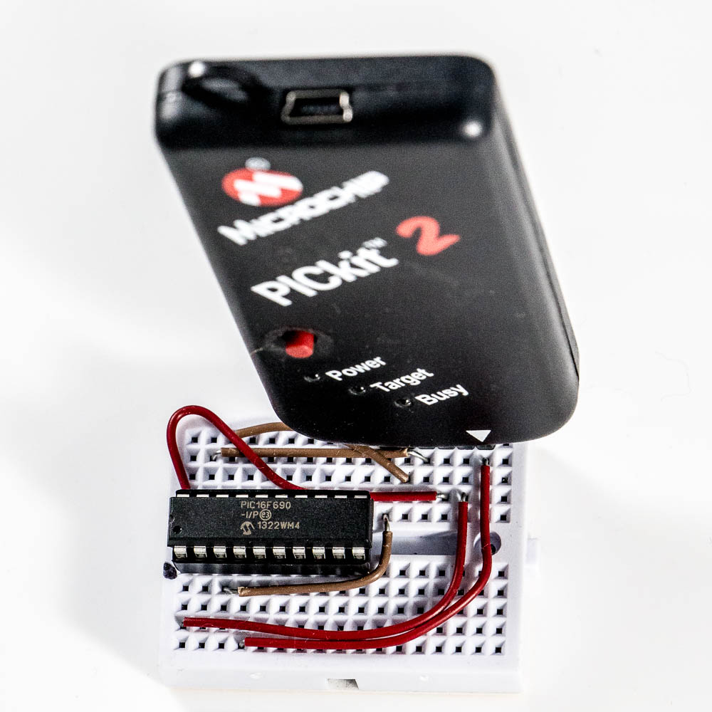
Then connect programmer to the computer and run PICKit programmer application on your computer:
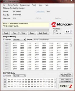
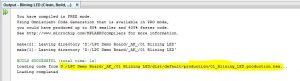
Now you need to go back to MPLAB X IDE (see Part I), open blinking LED project, do to Production menu and select Clean and Build Main Project. Now take a look at output and note location of HEX file:
Go back to PICKit programmer, File menu -> Import HEX and select file you just noted.
You should see note stating “Hex file successfully imported”
Now click Write.
You should see “Programming Successfull”
You can disconnect everything
And step 4:
get a new breadboard and create this:
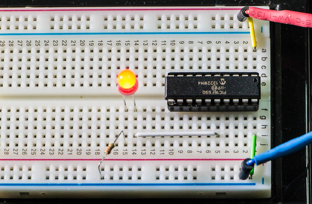
Once you connect power (5V) the LED should start blinking.